loading...
Introduction:
System Verilog is a Hardware description and verification language used to design, simulate, and test electronic designs. It is a superset of Verilog and standardized as IEEE 1800. It enhances a lot of powerful Verilog features. Its verification functionality is based on open Vera. It also uses a lot of constructs and features of C/C++. It is a class-based object-oriented programming language that has a lot of non-synthesizable constructs to provide a lot of flexibility for verification engineers to verify complex designs. It offers constructs that can be used to simulate HDL designs and validate them using high-level test cases.
System Verilog got its origins in 2002 when the startup business Co-Design Automation donated the Superlog language to Accellera. The majority of the verification functionality is built using Synopsys's Open Vera language. 2005 saw the adoption of System Verilog as IEEE Standard 1800-2005. The standard was combined in 2009 with the foundational Verilog (IEEE 1364-2005) standard to become IEEE Standard 1800-2009. IEEE standard 1800-2017 is the current version.
There are two unique functions that the System Verilog feature set can play: All capabilities of Verilog-2005 are available in System Verilog, which is an extension of that language used for register-transfer level (RTL) design. As a result, System Verilog includes Verilog in its subset. System Verilog, which is used for verification, is more closely connected to C++ than Verilog and makes considerable use of object-oriented programming approaches. Most of the time, these constructs may not be synthesized.
Why System Verilog?
In the 1990s, Verilog was the main language used to test the functionality of small, simple, and feature-limited designs. The need for better design and verification tools grows along with design complexity, hence System Verilog was introduced, which adds a robust, user-defined type system to Verilog for its enhancement. Moreover, it improves strong typing capabilities, particularly for user-defined types. Compared to Verilog, System Verilog is a more general-purpose language. It gives users the ability to define and package reusable functionality that is not already present in the Verilog.
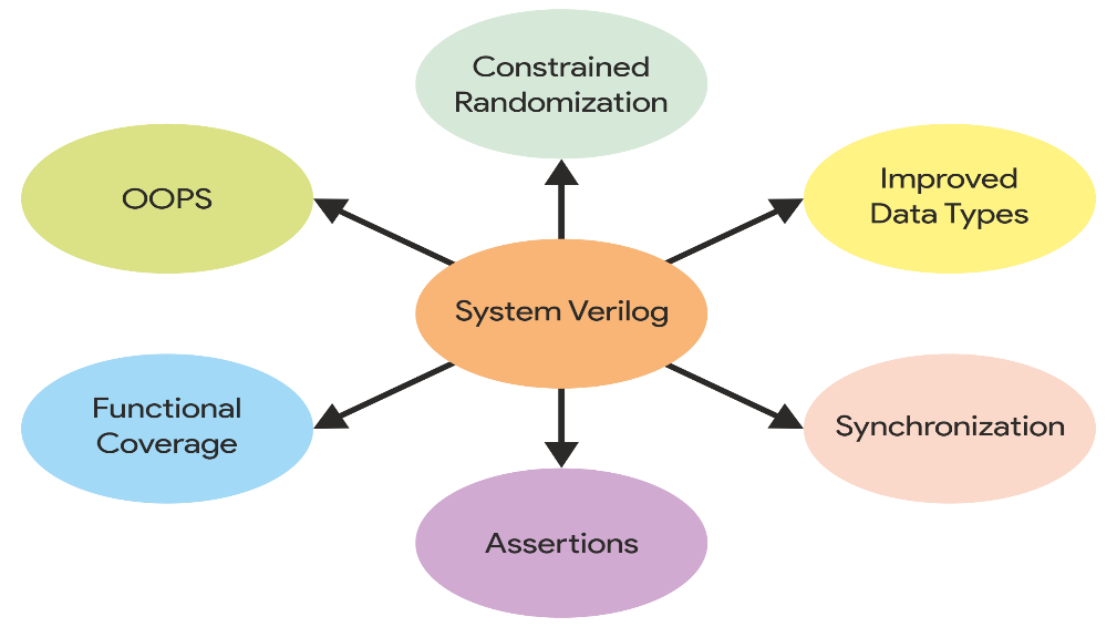
Figure 1: Features of System Verilog
Design verification and coverage analysis are common uses of System Verilog, which Verilog cannot handle as effectively. As shown in figure 1, Constrained random generation, assertion, and functional coverage constructs are among the features that System Verilog seeks to offer. Assertion-based verification, interface abstraction, and packaging are further capabilities added to System Verilog. System Verilog is a great tool for verifying the edge cases of the logic because of its object-oriented structure, which is exceedingly challenging or nearly impossible using Verilog.
Advantages of System Verilog:
The above section clearly emphasizes the importance of System Verilog as a Hardware Design and Verification language. It contains a variety of approaches that we may use for efficient verification. It has a separate region for the test bench and design. The further section will be explaining about the verification, test bench, and test bench architecture.
Verification is the process of making sure a specific hardware design performs as or not. The process of designing a chip is exceedingly intensive, time-consuming, and expensive to produce. Cost savings can be achieved by identifying functional design flaws at an early stage in the design cycle.
Testbench is used to check the functional correctness of the Design by generating and driving a predefined input sequence to a design, capturing the design output, and comparing it with respect to the expected output. The verification environment is a collection of classes that execute tasks, such as generating stimuli, driving, and monitoring. These classes are named according to their function. The hierarchy for the testbench is illustrated in Figure 2:
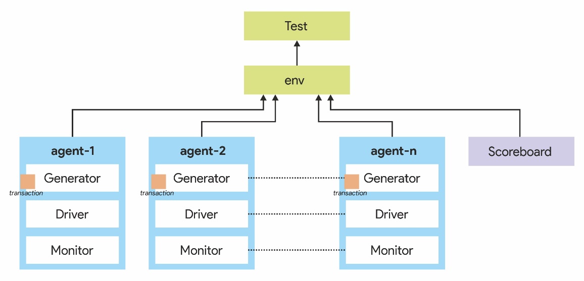
Figure 2: Hierarchy for System Verilog Testbench
Components of Testbench:
The System Verilog test bench has various components as shown in Figure 3 to perform a specific task.
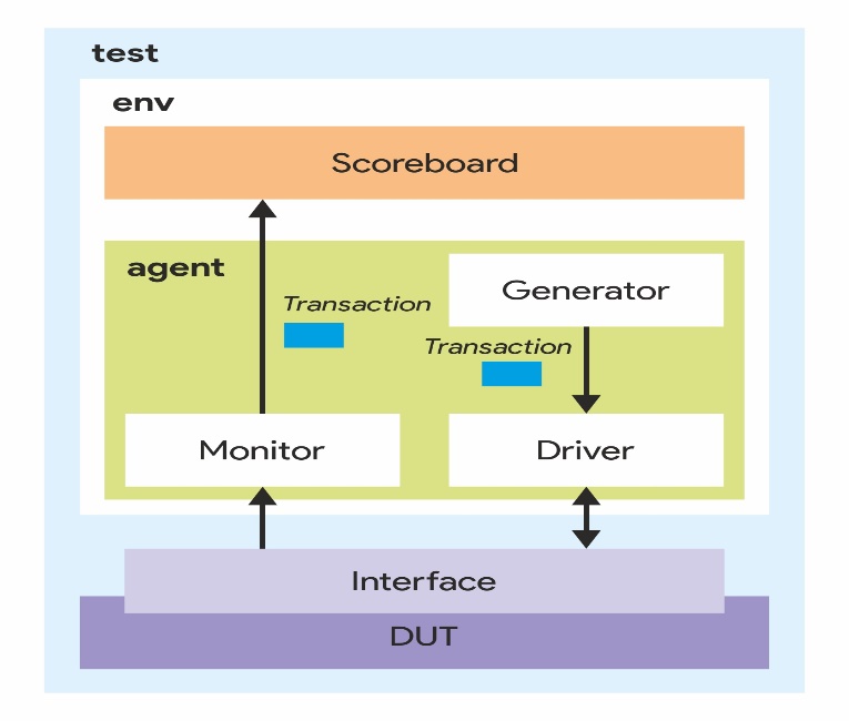
Figure 3: Components of System Verilog Testbench
 Verilog Essentials: Mastering the Fundamentals of Hardware Description Language
 Unleashing the Power of System Verilog: A Comprehensive Guide for Aspiring Designers
 Demystifying VLSI ch Design: Exploring the Core Concepts of VLSI Courses
 Basics of VLSI - An Ultimate Guide
 Career Prospects After Completing A VLSI Course
 Top 5 Reasons To Take Up A Professional VLSI Course
 Mastering VLSI Design: A Comprehensive Guide To Understanding Complex Integrated Circuits
 Future-Proof Your Career With A VLSI Course: How Learning About Integrated Circuits Can Boost Your Job Prospects?
 System Verilog: An Overview
 Introduction to Hardware Description Language (HDL)
 Unlock The Potential Of VLSI Design With An Integrated VLSI Course Online
 Universal Verification Methodology:An Efficient Verification Approach
 How to Write a Verilog Module for Design and Testbench
 What Are the Different Career Paths in the VLSI Industry?
 Skills required to establish a successful career in VLSI
 Looking for online VLSI courses? Futurewiz can fulfill your upskilling needs!
 The Future Of VLSI- Get All The Latest Insights!
 Super 50 Program For Advanced VLSI Design TrainingSteps to Build Career in VLSI
 Similarities between C and Verilog
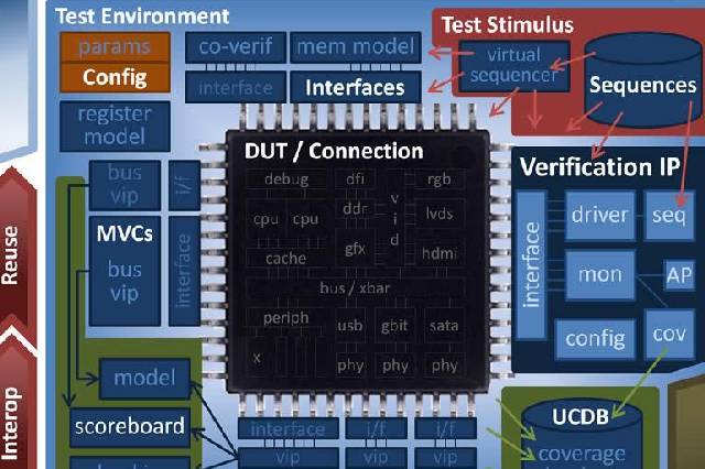 What is UVM - A High-level overview